Primer: Torsion bar suspension
- Jon Hawkes

- May 14, 2022
- 13 min read
Torsion bars are a simple and affordable technology and remain the most widely used suspension type in current generation AFV, though many if not most new build and next generation designs are making the switch to hydropneumatic configurations. They will remain a common if not majority feature of AFV design for decades to come, so here are some basics on what they are, how they work and how the way you make them can impact performance.
Contents:
Origin of torsion bars.
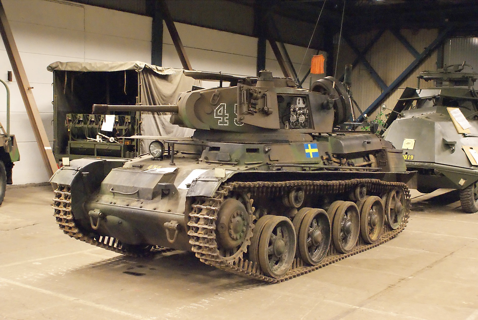
Torsion bars were first fielded in a motor vehicle in the Citroen Traction Avant car in 1934, and the same year the first military application was fielded, the Swedish Landsverk L-60 tank. More prominently were the German Panzerkampfwagen III, Russian KW-series and US M18 Hellcat, all widely fielded early adopters of this suspension type.
Though many, if not most, AFV through the 1930s and 1940s used spring based suspensions including Christie and Vertical/Horizontal Volute Spring (HVSS/VVSS) configurations, over time the torsion bar emerged as the default suspension configuration used in the majority of contemporary AFV, including the widely adopted Leopard 2, M1 Abrams and T-72 tanks, as well as most contemporary IFV and associated families including the CV90, BMP-series and M2 Bradley.

Torsion bar basics.
Contemporary torsion bars are typically circular section transverse bars with hexagonal or grooved/serrated ends and run across the floor of the hull, anchored on the opposite side to the road wheel that it is connected to. As the road wheel arm moves it twists the bar and this torsional resistance gives you a spring action thereby providing the desired travel and torque levels.
As a design concept it is simple, relatively light, and inexpensive, and these benefits have led to widespread adoption across most AFV of the past half century of more.
A practical design issue is that the bars have to lie across the bottom of the hull, and so create an effective raised floor before major assemblies such as the turret basket or engine compartment can be located, typically 100 mm to 150 mm in depth for a tank. Whilst that is itself obviously undesirable, the less immediately obvious ramification is a significant increase in weight, as the entire hull is higher, increasing structural and armour (as the whole hull has to be armoured) weight across the whole vehicle.

A further design consideration that is not immediately obvious is that using a torsion bar suspension configuration necessitates asymmetric running gear, as the bars run the full width of the hull and so prevent road wheels from being mounted on the same longitudinal position, instead being displaced from one another’s axes along the length of the vehicle.

This is not a significant issue from a design or automotive performance perspective but does add some additional design considerations to ensure uniform loading and balance through the suspension system. A limited number of vehicles have utilised shorter torsion bars in order to allow them to be anchored symmetrically on the centreline of the vehicle, including the Russian T-64. This results in sub-optimal spring characteristics and has been avoided by the vast majority of designers.

A few designs have utilised an angled torsion bar configuration, where the bars run at an angle allowing a symmetrical arrangement.
In addition to the bar itself, some, or all of a vehicle’s road wheel arms (generally the ‘outer’ wheels at the front and back of the vehicle) are fitted with shock absorbers to allow tuning of the suspension travel per road wheel and to assist in rapidly damping out vibrations that would otherwise pass through a 'pure' torsion bar setup to the hull as torsion bars do not have a self-damping ability.
Additionally, some or all road wheel stations will be fitted with bump stops to manage the behaviour of road wheels when they hit full travel as well as to prevent overstressing of the suspension system.

The bars and their mountings can offer limited adjustment, but for significant adjustment the bar is swapped out for one of a differing design. This can be seen for example when users upgrade Leopard 2A4 tanks to a later standard where the radical increase in weight over the front of the vehicle stemming from significant additional hull and turret armour packages as well as the larger L55 gun from the 2A6 series onwards necessitates the installation of stiffer bars in frontal road wheel stations.

Where minor adjustment is required, the bar end mounting of the bar can be twisted within its mounting to increase or decrease a pre-set tension level by actuation of a screw thread or hydraulic actuator acting on a lever to the end mounting, in effect presetting the bar to a defined level of 'twist'.
Torsion bar configurations have their drawbacks, chiefly that suspension travel is proportional to bar length and consequently hull width as well as being constrained by the material limits of the bar itself, though newer materials and production processes including electroslag remelted (ESR) steel, preening, presetting and surface finish rolling has upped travel limits from c.180 mm in immediate post war designs to beyond c.380 mm in contemporary designs. Sheer stress capacity has increased from early war-era designs at 200–300 mPa (though this was in large part constrained by poor quality steel) to a contemporary maximum in the region of 1,250 mPa.
If hull-width bars are unable to provide the required levels of sheer stress it is possible to increase the effective length using a tube-over-bar suspension system, whereby the torsion bars are each encased in a torsion tube, affixed in series with the bar by a spline coupling. The internal bar twists as usual, but at the opposing end to the road wheel it is coupled to the tube it is inside, so that then continues to twist all the way back to the road wheel side.
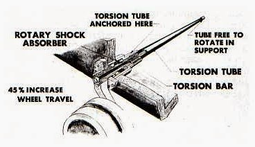
The overall spring length is therefore almost doubled (though the differing nature of applying torsion to a tube than a bar means the tube would need to be 11% longer than an equivalent bar to achieve literal doubling of length, based on failure torque), however such an arrangement carries the disadvantages of being more complex to mount within the vehicle, that the bar and tube have inherently differing spring characteristics to accommodate/align and that additional weight and space penalties are experienced, the latter seeing further space lost at the bottom of the hull to fit it as the complete assembly is of a thicker diameter.
That said, because the tube is affixed to the same side as the road wheel it is connected to, the system experiences less sensitivity to hull torsion than a conventional torsion bar system where the bars are mounted on the opposing side as may be affected as the hull twists under loading.

Tube over bar configurations became popular in the US in the 1960s and saw fielding in the LVTP7 amphibious APC and its iterative successor the AAV7 series, though the latter was converted to a conventional torsion bar arrangement taken from the M2/M3 Bradley IFV in the AAV7A1 Assault Amphibian Vehicle Reliability, Availability, Maintainability/Rebuild to Standard (AAV RAM/RS) overhaul programme carried out by BAE Systems carried out in the early 2000s.

An alternative is to effectively ‘fold’ the bars through a balance beam mounting and run a second bar back across the vehicle, again effectively doubling the length, but like tube-over-bar the design adds volume and complexity. This was fielded in the German Panther tank but saw little take up in the years since.

Ultimately, materials and production process improvements mean that a single torsion bar remains acceptably effective for the requirements of even the heaviest contemporary tanks, and as such double bars or tube-over-bar designs are not necessary, and this has been the near sole focus of torsion bar research and development since the 1970s.
A drawback of torsion bars is that torsion bars approximate the characteristics of a linear spring rather than the hardening spring profile that would be preferable to increase rebound force as the suspension approaches full travel.
Ideally, as the spring gets closer to the limit of its travel, you want it to get firmer to try and resist the force more and prevent it bumping its limit. As a result of this issue, advanced bump stops are typically utilised to provide nonlinear force around maximum travel.

An alternative is to fit some road wheel stations with an additional, smaller torsion bar of differing spring characteristic which is only actuated at the upper end of travel. The spring characteristics of the two bars provides for a graduated force-deflection curve rather than the linear characteristics of a torsion bar alone. This arrangement was used in the Vickers MBT Mk 4, later called the Vickers Valiant, which had secondary torsion bars located within the road wheel arms at stations one, two and six. The Valiant was developed between 1976 and 1984 but never entered production.
To combat potentially very high frictional stress at the point where the bars travel through the hull at the road wheel, they can be often run through an oil filled chamber. In most contemporary AFV with torsion bar suspension some or all road wheels are fitted with rotary dampers, which are mounted at this location for space efficiency and serve to further attune suspension characteristics.
Replacing bars, especially when they have been damaged, can be challenging and much more intensive than comparable replacement of externally mounted hydrogas units. Underbody blast damage from mines and IEDs can deform or fracture a torsion bar within the vehicle and removing it from the often-corroded anchor point can be challenging and time consuming.
Though a uniform surface is important to ensure consistent spring characteristics, precision straightness of the bar is, perhaps surprisingly, not statistically critical to efficacy, with a requirement for no more than c.1% Full Indicator Movement (FIM) over its length. This means that the bar can deviate laterally by up to 1% of its length without issue, meaning a typical c.2,100 mm torsion bar can deviate by up to 21 mm in straightness along its length without significant performance implications, not an inconsiderable divergence.
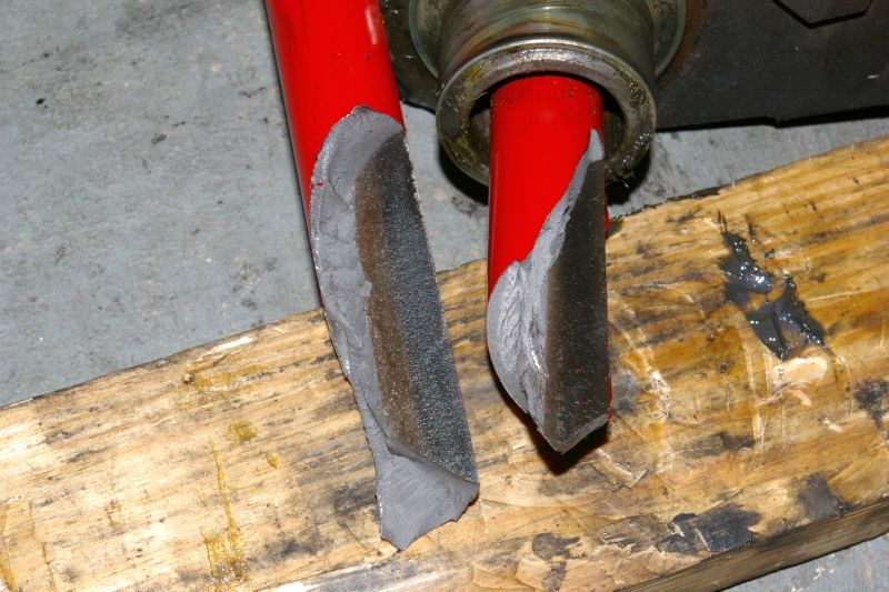
Torsion bars bring with them an inherent risk in that they are constantly mechanically loaded with energy, with most tank-type torsion bars holding up to 16,000 J of energy at full deflection. Should a bar fracture at such high levels of deflection, it can project fragments inside the vehicle with some significant force. A 500 g piece of bar can be propelled within the hull at up to 900 km/h in the event of a serious bar failure, potentially doing significant damage and injury. Such an event should be improbable, but damage or corrosion of the bar can result in failure under higher load profiles.
Underbody blasts can also present significant risks as bars can fracture, detach from their mountings, and be propelled within the hull causing secondary effects including significant injury and damage within the fighting and driver’s compartments, compounded by the aforementioned torsional loading. Modern mine protection packages typically include torsion bar ties to secure them in the event of them becoming detached.
As a component that is being repeatedly loaded with very high stressing forces, torsion bars have a limited effective fatigue life, after which they may deform or fracture. This fatigue life can be predicted reasonably easily through two primary factors – the maximum stress that will be experienced, and the initial stress. Fatigue life is of course tightly related to usage profile, with an extremely gentle profile offering several million cycles before failure, where extreme (and unrealistic) usage could see failure in as few as 200.
Typical values across normal heavy AFV usage for contemporary torsion bars are in the 65,000 to 90,000 cycles range . As a bar reaches its effective life limit, it can ‘settle’, essentially becoming preloaded in the direction of weight bearing and reducing the efficacy of that road wheel station as it has less resistance and travel.
Manufacturing torsion bars.
There are several key design and manufacturing considerations to the development of a high performing torsion bar, including the design, materials and manufacturing processes used. Broadly speaking, the application of a combination of the below factors will result in a typical contemporary high quality torsion bar of the kind used in most modern AFVs.
Materials.
Some attempts have been made to utilise materials other than steel, in particular titanium, which was used in the FMC Corporation XM800T Armored Reconnaissance Scout Vehicle (ARSV) built in 1972 . Though this made for very light bars, they were not superior from a spring characteristics perspective and their weight saving did not justify the manufacturing complexity and significantly higher cost. As a consequence, the concept has not been used other than in periodic experimental trials.

Profile.
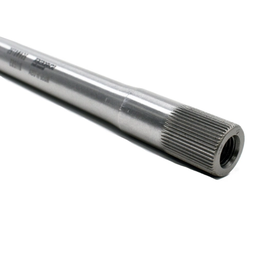
The end connector profile is the term given to the shape of the ends of the bar connecting to the road wheel arm and to the anchor hub within the hull. Each may be of a serrated or hexagonal profile to allow it to be affixed to the anchor or the road wheel arm and allow a rotational force to be applied to it. Both designs are widely featured, however a serrated profile permits the smallest end diameter without compromising the overall bar capacity.

In serrated designs, stresses within the ends of the bar can be very high, specifically in the serration root where the anchor first contacts the bar as well as localised pressures within the bearing surfaces of the serrations. Mitigating these stresses is typically achieved with a larger root radius, however this can increase pressure on the flanks and result in a root fatigue fracture, destroying the bar.
Hexagonal ends are attractive due to simplicity and speed of automated machining. An important design factor is to ensure that the hexagon flats and corners are precisely machined. Excessively rounded corners can result in a cam action within the anchor, which in extreme scenarios can catastrophically fail by bursting the anchor hub.
The transition section is the portion of the bar where the profile changes from a uniform circular cross section to the serrated or hexagonal profile of the end connector. End connectors are narrower than the main bar profile, and so a tapering is required. This is typically around 30° when a straight taper is used, or where an arc taper is used it is normally set at a radius of four times the bar diameter.

Excessively sharp angles within the transition section risk stress concentrations and consequent fatigue fractures and bar failures. As a result, smooth tapers are desired over notches or sharp angles - a notched bar profile can see up to a 44% reduction in their fatigue limit versus a smooth or tapered profile bar. This can be mitigated by surface treatments such as peening or surface rolling.
Treatments.
Following initial manufacture, torsion bars need to be heat treated to improve certain characteristics including hardness. Highly stressed bars of the type used in AFV suspension, particularly those that include machining, forging or other finishing of end profiles and serrations prior to heat treatment need to be carefully heat treated in a controlled atmosphere furnace, a neutral salt bath or using electrical methods which minimise pitting, scaling or surface decarburisation during the heating process.
Quenching is generally completed in oil, held at a temperature of 40°C to 80°C. This quenching is carried out either with bars hanging vertically (like the components being quenched in the video above) or by spinning them during the process to ensure that they remain straight and do not distort. Following quenching, torsion bars are immediately moved to a tempering furnace to further control the cooling and insure that surface defects including cracking do not form.
Peening, or shot peening, is a process intended to confer resistance to metal fatigue and to some forms of stress corrosion in the surface of a torsion bar, or indeed any metallic object. It is achieved by striking the surface of the bar with shot (made from cast steel, cut wire, ceramic beads, or glass), typically propelled by high pressure air and centrifugal wheels.
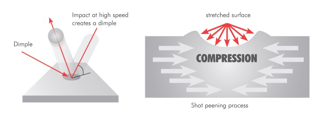
The process is outwardly similar to sandblasting, but the differing shot size (larger) and velocity (lower) mean it is operating by plasticity rather than abrasion, with each shot acting rather like a very small ball-peen hammer hitting the object, hence the name.
The technique is used extensively in the manufacture of high stress automotive components including springs, crankshafts and connecting rods. The compressive residual stresses formed by the work hardening of the shot peening substantially reduce the rate of initiation and propagation of cracks in the surface of torsion bars, significantly extending their useful fatigue life and lowering risk of failure .
A secondary benefit of peening is that it inhibits settling of the suspension, which simplistically is where the torsion bar sags (becomes preset) in the direction of travel by sustained loading, resulting in loss of travel and degraded suspension performance over time.
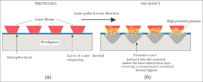
Developments in peening technology also offer ultrasonic impact peening (UIP)/ultrasonic shot peening (USP), wet shot peening and laser shock peening (LSP), the latter utilising high energy pulsed lasers to impart a shock into the surface of the object being peened instead of the kinetic impact of shot in traditional peening. Dating back to the late 1960s, LSP offer potential improvements over traditional shot peening with four to five times deeper residual stresses into the material surface, a higher intensity of stress and with greater uniformity over the surface.
Torsion bars are often further treated with surface rolling, a process used extensively in the manufacture of highly stressed and friction components such as crankshafts. As a mechanical surface treatment, surface rolling imparts compressive residual stress into the surface layers of the bar, resulting in higher resistance against fatigue loading, crack formation and propagation , and wear, as well as increased corrosion resistance.
Surface rolling has been demonstrated to be more effective in broad terms than shot peening, with residual stresses that extend deeper into the material . In addition to this, the surface rolling treatment leaves a much smoother, glossy, surface without the imperfections of shot peening and potential vulnerability to short cracks and surface corrosion . Surface rolling can be carried out on peened bars to mitigate these imperfections, but generally is considered an exclusive alternative rather than an iterative manufacturing process.
Presetting, also known as prestressing, bulldozing or scragging, is a manufacturing process that allows the bar to tolerate operating stresses higher than the initial elastic limit of the material in a pre-determined direction of rotational torsion, consequently increasing the load capacity of the bar. In plain English, its lets the bar be stronger than it naturally is.

In principle, it is a similar treatment concept as autofrettage in tube manufacture such as gun barrels. It is strictly directional and the presetting process will also reduce the tolerance of the bar in the opposing direction, and as such the operational torque must always be applied in one direction and never be reversed. This means preset torsion bars are made and labelled for one side of the vehicle only, and a user cannot install a clockwise bar that has been set for one side of a vehicle into the other, counter clockwise, side.
Presetting is applied by taking a newly formed bar and twisting it to a specified angle contrary to the direction of normal movement when in use, release and then repeat at least two more times. The effect is to apply a radial strain into the bar against the expected direction of travel that decreases stresses during operation in the highly stressed outer boundary (or skin) of the bar where the elastic limit will be reached first and failure will generally occur, instead applying greater stresses to the lightly loaded core. The result is a greater load capacity and longer fatigue life, thanks to an increase in nominal shear stress of c. 20%.
Research has shown that the order in which treatments are applied is significant . Presetting should take place after surface finishing, either by shot peening or surface rolling, otherwise the process of surface finishing the bar reduces its ability to sustain service loads compared to one that is surface finished and then preset. It should be noted, however, that the presetting process obliterates a significant degree of the shear forces set into the material by the surface finishing process, and that there is no process by which a straightforward stacking of stresses can be achieved.
Summary.
Torsion bars are a simple and affordable approach to tracked AFV suspension, and despite dating back to the 1930s, are still the overwhelming standard option for AFVs. That being said, they have essentially reached their practical limits in terms of development within modern metallurgy and design space, with hydropneumatic systems (to come in a later primer) becoming the preferred option for high end new build AFV due to a range of benefits particularly around greater internal space, better survivability, improved ride (particularly with respect to reduced noise and vibration) and improved mobility as a whole thanks to the ability to adjust any or all road wheels individually as required including as a fully active suspension system.


Thanks a lot...very informative article
Request you to post a similar type of article on runnning gear (track, road wheel and sprocket) of tracked vehicle